Unstable slopes and aging tank foundations are among the highest-risk assets on any industrial site. A few millimetres of unnoticed movement, repeated over weeks or months, can eventually lead to landslides, tank tilt, foundation cracking or loss of containment. Traditional visual inspections and periodic total-station surveys are labour-intensive, weather-dependent and often miss the early stages of deformation.
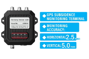
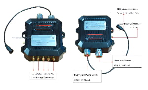
The Slope & Tank Deformation Monitoring solution uses static GPS RTK sensors and a local reference station to measure displacement of slopes, embankments, retaining walls and tank foundations with millimetre-level accuracy. Each monitoring node continuously tracks its position relative to the reference station and reports changes in three dimensions – vertical settlement, horizontal movement and tilt – through an industrial communication gateway to the central platform.
The system is designed for harsh industrial environments such as open-pit mines, waste dumps, highway or rail cuttings, tailings facilities and oil tank farms. Hardware is fully outdoor-rated and supports continuous operation under rain, dust, temperature swings and vibration. When displacement exceeds configured thresholds, the system automatically generates alarms, visualises the affected area on the map and can notify operators by SMS, email or integration with the DCS / safety system.
Compared with periodic surveying, this architecture provides 24/7 deformation monitoring and a continuous history of displacement for every slope or tank. It allows engineers and safety teams to detect slow trends early, plan targeted inspections, adjust loading and schedule remediation work before a minor movement becomes a major incident.