Skip to content
Industrial UWB RTLS for Real-Time Visibility
Menu

JCZD — Industrial Monitoring Terminal

A high-precision GNSS-based monitoring terminal designed for real-time displacement and settlement monitoring in landslides, mining slopes, dam structures, reservoir embankments, tank subsidence, and roadbed deformation. Accuracy: ±2.5 mm horizontal / ±5 mm vertical. Supports GNSS differential positioning, 4G/RJ45 communication, fusion positioning algorithms, and outdoor IP67 deployment.

SKU: JCZD001
GPS subsidence monitoring terminal JCZD device front view showing model label and indicator panel.

Transmission & Network

Primary Transmission
Ethernet (RJ45)
Network Topology
Wired

At-a-Glance

Positioning Technologies
GNSS/Beidou
Frequency Band
1–10 Hz
Communications & Interfaces
RJ45 (Ethernet), 4G
Power Input
DC 6V / 0.5A
Hot-swappable Battery
No
Ingress Protection
IP67
Explosion-proof Rating
EX ib IIC T4 Gb
Operating Temperature
−40 °C to +80 °C
Dimensions
122 × 137 × 45 mm
Weight
< 1.2 kg
Accuracy: 3cm
Temp: -40~80°C
Weight: 1200g

Description

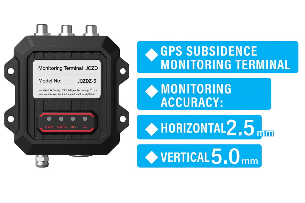
The JCZD monitoring terminal is an industrial-grade high-precision GNSS monitoring device developed based on static GNSS differential technology. It achieves ±2.5 mm horizontal and ±5 mm vertical accuracy, making it ideal for real-time monitoring of micro-displacement and settlement in harsh outdoor conditions.

It is widely deployed in:

  • Landslides & geological hazards

  • Mining slopes & open-pit deformation
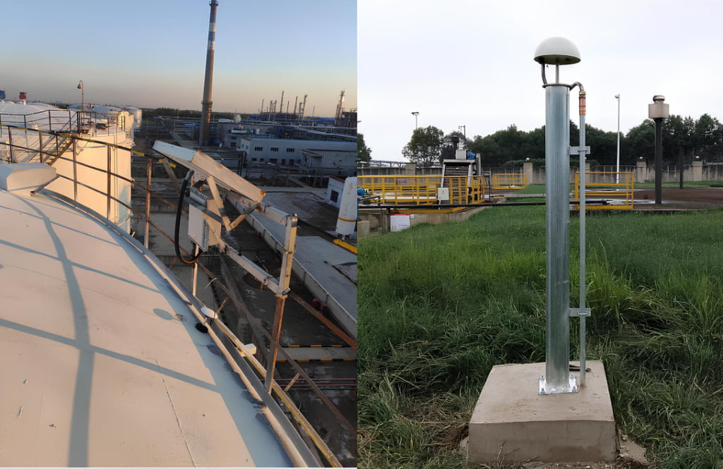
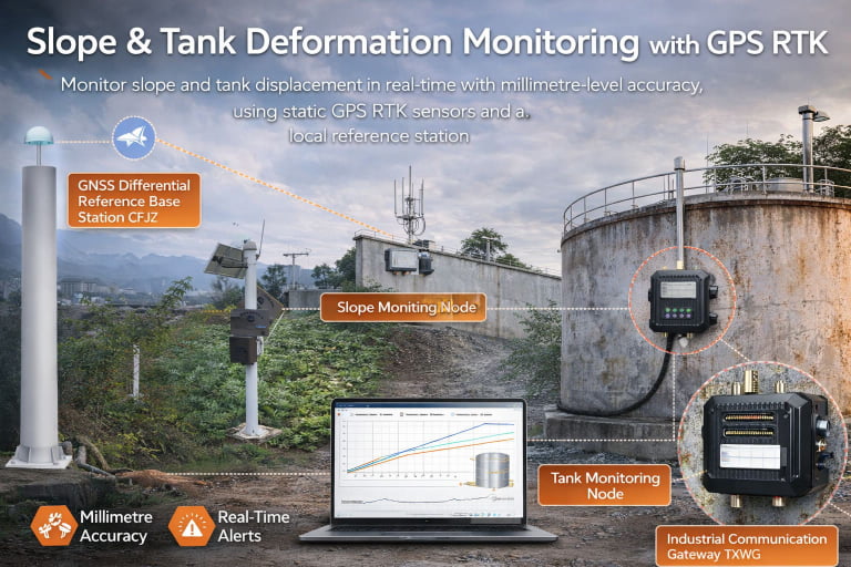
  • Oil tank settlement

  • Dam & reservoir embankment settlement

  • Roadbed displacement monitoring

  • High-precision structural monitoring

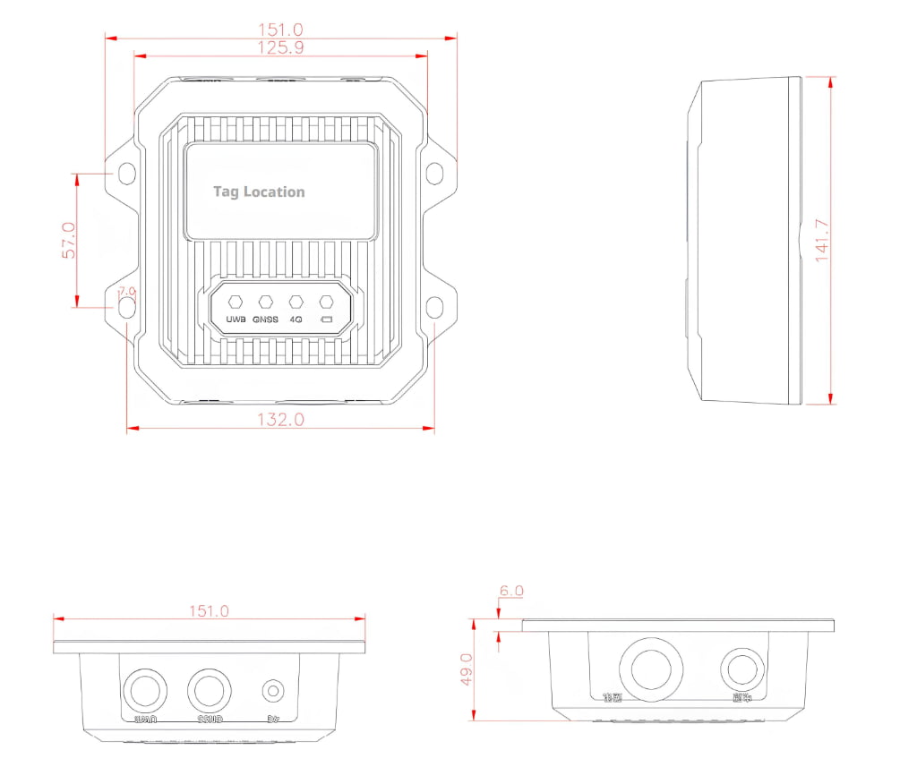
With its aluminum alloy housing, IP67 protection, GNSS fusion algorithm, and stable 4G/RJ45 communication, the device supports long-term 24/7 unattended operation.


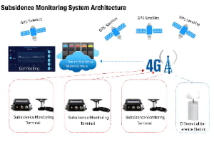
System Architecture Overview

1. GNSS Data Acquisition

Each JCZD terminal continuously receives multi-constellation GNSS satellite signals (GPS, Beidou optional, GLONASS).

2. Differential Positioning

Using static GNSS differential technology, the system corrects GNSS errors through:

  • Internal fusion algorithms

  • Optional reference base station

  • Multi-system satellite correction data

3. Communication Layer

Data can be transmitted through:

  • 4G Full Netcom (built-in SIM)

  • RJ45 Ethernet

Ensuring real-time communication between terminals and cloud servers.

4. Cloud Monitoring Platform

The backend server performs:

  • Fusion positioning

  • Multi-point settlement analysis

  • Trend prediction

  • Data visualization

  • Early-warning alarms

5. Monitoring Deployment Modes

The system supports:

  • Single-point vertical settlement

  • Multi-point cross-section displacement

  • Multi-terminal networked monitoring

  • Solar-powered remote deployments

Subsidence monitoring system architecture including GPS satellites, monitoring platform, JCZD terminals, and differential reference station


Typical Application Workflow

  1. JCZD terminal fixed on pole / structure

  2. GNSS antenna collects satellite signals

  3. Device performs fusion + differential positioning

  4. Data transmitted via 4G/RJ45 to cloud platform

  5. Platform visualizes real-time displacement curves

  6. Automatic alerts when thresholds are exceeded


Specifications

Power InputDC 6V / 0.5A
Indicator Lights4 LEDs
Positioning SystemGNSS full system (Beidou optional)
Positioning Frequency1–10 Hz
Static AccuracyHorizontal: ±2.5 mm + 1 ppm; Vertical: ±5 mm + 1 ppm
GNSS AntennaExternal antenna
Positioning AlgorithmFusion positioning algorithm
4G CommunicationFull-Netcom (internal SIM)
Housing MaterialAluminum alloy
Device Dimensions122 × 137 × 45 mm
Device Weight< 1.2 kg
Operating Temperature−40 °C to +80 °C
Operating Humidity0%–90% (non-condensing)
Explosion-Proof MarkingEX ib IIC T4 Gb
Communication Methods4G / RJ45
Protection LevelIP67

Values are typical unless stated otherwise.


Wiring & Connections

Connectors

RJ45

Installation

JCZD GPS subsidence monitoring equipment installed on industrial tanks and monitoring platforms.

Compatible / Accessories


Mechanical Drawings

Z collision avoidance radar device dimensions showing front, side, and bottom measurements for installation reference.

🌍 Industries where this device is deployed

FAQs

Procurement (Device & Data Layer)

Shortlisting devices? Get an RFQ-ready BOM path.

Move from product selection to an actionable RFQ: scope boundaries, terms, lead time, and deliverables.

Ready to Deploy RTLS?

Share your site layout and accuracy needs--we'll suggest a practical setup.

Contact Us